Poking pixels into screen memory in the Acorn Electron version of Elite
When the Apple II came out in 1977, its high-resolution colour graphics were genuinely impressive. The story of how Steve Wozniak managed to coax colour out of what is essentially a black-and-white machine is a fascinating read, and I highly recommend the Nicole Express article Apple II graphics: More than you wanted to know for an entertaining dive into how Woz cleverly used the NTSC colorburst to break new ground and add high-resolution colour to the Apple's graphics.

I won't re-hash any of that here: it's mind-bending stuff and is better covered elsewhere. Instead, I'll look at how Elite draws high-resolution pixels on-screen by poking data into the Apple's intriguing screen memory layout, giving us an almost (but not quite) monochrome space view and a very colourful dashboard.
Text vs graphics
----------------
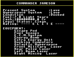
Before we talk about pixels in the high-resolution screen mode, I should mention the game's text screens. They look like this:

while the rest of the game looks like this:
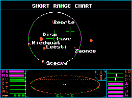
This is because the text-based screens use the Apple's built-in text mode rather than the high-resolution graphics mode, and that's a result of the Apple version's space view not being tall enough to fit all of the text into the portion of the screen above the dashboard.
The Commodore 64 version has the exact same problem, which it solves by removing the dashboard and using the whole screen for displaying text. This works well, and there's enough memory to store a copy of the dashboard image that we can put back into screen memory when we return to the space view.
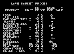
But the Apple II version doesn't have enough spare memory to store a copy of the dashboard, and besides, drawing letters on-screen in the high-resolution screen mode produces text that can be difficult to read, due to the colour fringes that we'll be talking about later. So the Apple version takes a different approach, and uses the text screen mode to display the text-based screens like the Market Prices view:
For the rest of this article, we're going to be talking about high-resolution graphics screens, rather than the text screens.
Drawing monochrome pixels in the space view
-------------------------------------------
We'll talk about colour graphics on the Apple II in a moment, but for now let's pretend that the Apple's high-resolution screen mode is monochrome, and that we are drawing pixels in the space view into this monochrome screen mode. (This isn't inaccurate, as the high-resolution graphics mode is actually a monochrome screen mode... but let's leave that discussion until later.)
In this monochrome screen mode, each bit represents one pixel. A set bit (1) represents a filled foreground pixel, and a clear bit (0) represents a black background pixel. On an old-school green screen, the filled pixel would be green and the background would be black, while on an old-school amber screen the filled pixel would be amber and the gap would be black.
Elite can therefore draw pixels in the space view by simply setting the relevant bits in screen memory, and that is exactly how the drawing routines work. This is conceptually no different to drawing in monochrome on the BBC Micro: see the deep dive on drawing monochrome pixels on the BBC Micro for more about that. But the structure of the high-resolution screen memory in the Apple II is completely different to the BBC Micro (and all the other 6502 versions), so let's take a look at that now.
As with all the pixel-plotting routines in Elite, the Apple II version of the PIXEL routine has to do two things: first, we need to work out the address in screen memory of the byte that contains the pixel that we want to plot, and second, we need to draw that pixel by poking a set bit into the correct place within that byte. And on the Apple II, neither of these processes are particularly simple, especially if you're used to the logically ordered screen modes of the BBC Micro, Commodore 64 and NES.
So let's break this down into three stages: pixel lines, then the pixel bytes within those pixel lines, and then the pixel bits within those pixel bytes.
Pixel lines
-----------
The Apple's high-resolution screen layout is described in this oft-quoted diagram from page 21 of the 1981 edition of the Apple II Reference Manual:
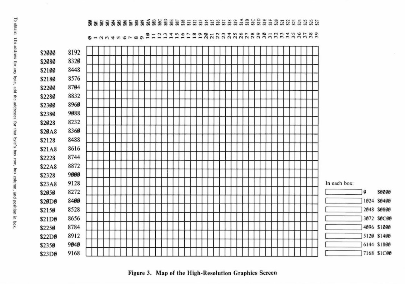
This shows 24 eight-pixel high character rows, each of which contains 40 eight-pixel wide character blocks, and that is indeed what the screen looks like. But if you look more closely at the addresses down the left side, and the breakdown of each character block in the bottom-right, then it's apparent that screen memory is laid out in a very different manner.
It's probably easier just to think of the Apple's screen memory as being made up of pixel lines, each of which stretches from the left side of the screen to the right. Despite what it says in the above diagram, there aren't really any character blocks on the Apple, just pixel rows, although it is useful to think of these pixel rows as being conceptually grouped into 24 eight-pixel high character rows, like the character rows of the BBC Micro and Commodore 64.
Each pixel line is mapped to a continuous part of memory, so to move along from the left end of the line to the right end of the line, we simply work out the address of the first byte in the line, and then each consecutive byte in memory maps to the pixels in the line as we go from left to right. Each pixel line contains 280 pixels, so that's 280 bits of information stored in each pixel line, with one bit per pixel.
So far, so good, except now we come to the surprising part; well, three surprising parts, actually.
First, as noted in the above diagram, the addresses of each of these pixel lines in screen memory are... interesting. The pixel lines don't appear one after the other in memory; they are interleaved in a way that does have a logic behind it, but it's honestly just easier to ignore the actual addresses and use lookup tables, so that's what Elite does.
There are two lookup tables, SCTBH and SCTBL, that convert the number of a character row (0 to 23) into the address shown on the left in the above diagram. This is the address of the start of the first pixel line in that character row, and there are 24 character rows on-screen, each being eight pixels high, so that's a vertical resolution of 192 pixels.
The eight pixel rows within each character row are interleaved, so that each pixel row appears $400 bytes after the previous pixel row. This means that if the address of the first pixel row in the character row is in (SCTBH SCTBL), then the addresses of all eight pixel lines in the character row are as follows:
- Pixel row 0 is at address (SCTBH SCTBL)
- Pixel row 1 is at address (SCTBH SCTBL) + $400
- Pixel row 2 is at address (SCTBH SCTBL) + $800
- Pixel row 3 is at address (SCTBH SCTBL) + $C00
- Pixel row 4 is at address (SCTBH SCTBL) + $1000
- Pixel row 5 is at address (SCTBH SCTBL) + $1400
- Pixel row 6 is at address (SCTBH SCTBL) + $1800
- Pixel row 7 is at address (SCTBH SCTBL) + $1C00
This is what's shown in the bottom-right corner of the reference manual diagram, and it enables us to work out the address of the start of any pixel line on-screen by looking up the address from (SCTBH SCTBL) and adding the correct multiple of $400.
One of the things that we often do when drawing lines is to move from one character row to the next. Moving down is easy enough - we just look up the next character row's address in the SCTBH and SCTBL tables - but if we want to move up from the top pixel row in one character row to the bottom pixel row in the character row above, then we would need to look up the previous character row's address in the SCTBH and SCTBL tables, and then add $1C00 to get the address of pixel row 7 in that character row. To save having to do this calculation manually, the table at SCTBH2 contains the address from SCTBH but with $1C00 already added to it, so we can fetch the high byte of the address of the last pixel row in the character row with a single lookup.
So that's the first surprise dealt with, and we can now use these lookup tables and some simple addition to get the start address of any pixel row in memory.
Pixel bytes and pixel bits
--------------------------
The second surprise is that although the pixel bytes in each pixel row contain eight bits each, those eight bits don't represent eight pixels. Instead, each pixel byte represents seven pixels, and bit 7 in each pixel byte is reserved (we'll see why later). So taking the very first pixel row on the screen, at address $2000, we have seven pixels in the first byte, seven pixels in the second byte, seven pixels in the third byte, and so on until we reach the 40th byte, which contains the last seven pixels, giving a total horizontal resolution of 40 * 7 = 280 pixels. Compared to the more common eight pixels per byte of screen memory, this is very strange indeed.
The challenge, then, is to work out which byte in the pixel row contains the pixel that we want to update. The maths is simple enough: if we want to plot a pixel at x-coordinate x, then we need byte number x div 7. But while this calculation is easy to write down, it's a pig to implement in assembly language (unlike the equivalent calculation for the BBC Micro's screen layout, x div 8, which can be implemented in just three right shifts).
The third (and final) surprise is how the bits within each pixel byte map to the pixels on-screen. We've already mentioned that bit 7 is reserved, so let's ignore that bit for now. We therefore have seven bits of information that represent seven pixels on-screen... but they aren't in the order that you might expect. The leftmost pixel on-screen is controlled by bit 0 in the pixel byte, the next pixel to the right is bit 1, then we have the pixel for bit 2, and so on until we get to the pixel for bit 6 at the right end of the pixel byte. This is a different order to most bitmapped screens, including the BBC Micro and Commodore 64, where the bits on-screen match the order in which humans write them down.
Luckily we can hide all the complexity of the last two surprises in lookup tables - in this case the SCTBX1 and SCTBX2 tables. These can be used to convert a pixel x-coordinate into the number of the corresponding pixel byte on the pixel row, and the bit number within that byte of the pixel in screen memory. Specifically, given a pixel x-coordinate X in the range 0 to 255, the tables split this into factors of 7, as follows:
X = (7 * SCTBX2,X) + SCTBX1,X - 8
Because each byte in screen memory contains seven pixels, this means that SCTBX2,X gives us the byte number on the pixel row, and SCTBX1,X is the bit number within that byte. And because the Elite game screen is only 256 pixels across (with the border box flanking this playing area), we only need to convert x-coordinates in the range 0 to 255, making the lookup process easy to implement in 6502 assembler using indexed addressing.
You can see all this in action in the PIXEL routine. It starts by fetching the address of the relevant pixel row from (SCTBH SCTBL), and then it fetches the byte number from SCTBX1 and the bit number within that byte from SCTBX2. The routine is made slightly more complicated by the need to draw different size dots depending on the distance (as this routine is used for drawing stardust, amongst other things), but it does demonstrate the use of the lookup tables.
So that's how we can draw pixels in the monochrome space view, and once we have pixels, we can draw stardust and ship wireframes and text and circles and suns and all the other things that make up the Elite space view.
Except this isn't the full story, so let's bite the bullet and talk about colour.
Drawing in colour
-----------------
You probably noticed that the space station in the screenshot above isn't actually monochrome. Take another look:
Some of the lines in the station are white, but most of them are definitely coloured in some way. Because although the Apple's high-resolution display is a monochrome display with a one-bit-per-pixel bitmap, it decides to display some of these monochrome pixels in colour when connected to an NTSC TV screen.
The colours aren't set in a traditional way, but they are inferred from the pattern of monochrome pixels. If the computer has a monochrome screen, then the space view will appear in monochrome, with set bits being filled and clear bits being black. But the exact same screen in memory, when shown on an NTSC television, will appear in colour. It's completely different to the way most home computers work, and it's all part of the genius of Steve Wozniak, that he managed to coax colour graphics out of a monochrome computer.
The rules that determine how the NTSC screen displays our monochrome bitmap in colour are a bit strange, but by this point that's probably not a surprise. Here they are, taken from page 19 of the 1981 edition of the Apple II Reference Manual (where "off" bits are clear, "on" bits are set and the "undisplayed bit" is bit 7 in each pixel byte):
A total of 280 dots are displayed on each of the 192 lines of the screen.
If a bit is "off", its corresponding dot will always be black.
If a bit is "on", however, its colour will depend upon the position of that dot on the screen, as follows:
- If the dot is in the leftmost column on the screen, called "column 0", or in any even-numbered column, then it will appear violet.
- If the dot is in the rightmost column (column 279) or any odd-numbered column, then it will appear green.
- If two dots are placed side-by-side, they will both appear white.
- If the undisplayed bit of a byte is turned on, then the colours blue and red are substituted for violet and green, respectively. Thus, there are six colours available in the High Resolution Graphics mode, subject to the following limitations:
Each byte must be either a violet/green byte or a blue/red byte. It is not possible to mix green and blue, green and red, violet and blue, or violet and red in the same byte.
- Dots in even columns must be black, violet, or blue.
- Dots in odd columns must be black, green, or red.
- Two coloured dots side by side always appear white, even if they are in different bytes.
I found this pretty difficult to follow on first read, and it also omits a crucial bit of information - how continuous blocks of colour are formed. So here are the same rules, but explained in a way that I find a bit easier to understand:
- Whenever you see a clear bit (i.e. 0), then it's always a black pixel (though see the last point below).
- Whenever you see a sequence of two or more set bits (i.e. 11, 111, 1111 and so on), then all those set pixels are always white.
- Whenever you see a single set bit that's surrounded by zeroes (i.e. 010), then the pixel in the middle is coloured (i.e. violet, green, blue or red) while the pixels on either side are black (though see the last point below).
- The colour of the single set bit depends on two things: whether the pixel's x-coordinate is odd or even, and the value of bit 7 in the pixel byte where the set bit appears:
- If bit 7 is clear (i.e. 0), then pixels with even x-coordinates are violet and pixels with odd x-coordinates are green.
- If bit 7 is set (i.e. 1), then pixels with even x-coordinates are blue and pixels with odd x-coordinates are red.
- Whenever you get two or more single pixels of the same colour in a sequence (e.g. 01010 for black-violet-black-violet-black, say), then the colour from those pixels "bleeds" into the black pixels that are "trapped" between them, so in this sequence, the middle black pixel would appear on-screen as violet, thus producing a line of continuous colour.
The colour-bleed and banding in the last point is caused by the TV set not being quick enough to turn its beam intensity on and off cleanly at that frequency, so the two colour pixels blur together, even though they are separated by a black pixel (i.e. a clear bit) in screen memory; as a result, the "trapped" black bits tend to appear on-screen as light-dark bands of the bleeding colour. For more detail on this, see page 8-19 of Understanding the Apple II by Jim Sather, which digs really deep into the whole colour-generation system.
These rules explain why some of the pixels in the space station appear in violet and green: they are one-pixel wide lines, which appear in the bitmap as 010. The green pixels appear when the set bit is in an even column, and the violet pixels appear when the set bit is in an odd column. When drawing lines and pixels in the space view, we always keep bit 7 clear, so we only see violet and green colour fringes, and not red or blue.
Filled colour
-------------
The violet and green colour scheme doesn't apply to the sun, though, which is a glorious orangey red. This is because the sun-drawing routine sets bit 7 in each of the sun's pixel bytes and draws the sun lines using the pattern 1010, making sure that the set bits appear in odd columns. This produces a red colour, with the red pixels (from the set bits) bleeding into the adjacent black pixels (from the clear bits) to create a red sun with a distinctive banding effect:

You can see some interesting effects where the white laser sights overlap the sun. For example, when they're in front of the sun, the vertical sight lines appear as two white pixels followed by two black pixels. This seems odd, but it's an example of the EOR logic in action. The vertical sight line is made up of two set pixels so that it appears in white, so that's a pattern of 0110 when it's drawn on the normal black background of the space view (and this four-bit sequence happens to be drawn with it starting in an odd column). The sun, meanwhile, has a bit pattern of 1010, with this also starting on an odd column (so the first set bit is red).
When these two are combined together on-screen using EOR logic, they combine into 0110 EOR 1010 = 1100, which gives us two white pixels followed by two black pixels. And because the 1100 starts on an odd column, the red pixels around each side fit in nicely without any gaps or other fringe colours. Finally, because the pixel byte showing the vertical sight changes from 0110 to 1100, the vertical line moves left by one pixel compared to when it isn't in front of the sun.
So that's the space view, but what about the dashboard? Well, unlike the BBC Micro, Commodore 64 and NES versions of Elite, the Apple II version doesn't need to use a split screen to implement a colour dashboard as the lower part of the screen can already handle it, so the dashboard follows the exact same rules when it comes to colour. But unlike the space view where the colour is an unintentional side effect of drawing one-pixel wide lines, the colour in the dashboard is intentional.
The main routine used to draw the dashboard indicators is HLOIN, which draws a horizontal line in a specified colour. It's made quite complicated by the need to spread alternating colour sequences (0101 or 1010) over multiple bytes and in chunks of seven bits, but that's the Apple II for you: simplify the hardware and move the complexity into software.
And it doesn't get much more complex than the Apple II high-resolution screen mode...